|
|
|
Who's Online
There currently are 6043 guests online. |
|
Categories
|
|
Information
|
|
Featured Product
|
|
|
 |
|
|
There are currently no product reviews.
 ;
I am very happy regarding the online purchase of this manual from Owner-Manuals.com as with this I could set right my Denon CD player and Amplifier.
I once again sincerely thank them for the prompt service which was rendered to me.
N. Shanker
;
More than pleased with my prurchase, very good product for the price.
;
Manual-link came 30 minutes after having paid for an extremely rare (40 years old) item (sony icr-120) and helped me to get the radio rework again. So really good help for me, fast and reliable delivery and -taken that into consideration- a very reasonable price for that service. So thanks again! Mike, Germany
 ;
Some of the pictures in this manual are a bit irritating. I had to dissassemble the unit and some of the screws have different threads, which is not mentioned in this manual. Also some of the drawings of the boards look different than the actual boards.
After all, the manual was very useful. I was able to recalibrate the capstan drive and it is working fine again.
;
This manual is very good. 303 pages scanned in a very high resolution. My camera has bad, leaking capacitors which all of the V5000 models are suffering from these days.
There is a huge part list with all capacitors, transistors etc. in this manual which helped me a lot. Otherwise I would not have been able to buy replacement parts.
The dissassembly guide is very enormous and detailed. Unlike on the Panasonic MS1 manual I downloaded here it actually looks like the real parts look. And the screws are labeled correctly, so you shouldn't have any left after the repair. ;)
2-1
2-1
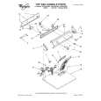
DISMANTLING INSTRUCTIONS
Dismantling of the Front Panel assembly 1) Loosen the 9 screws to dismantle the Top Cover (pos 252) - 2 screws on each side - 5 screws on the Rear Panel (pos 251). 2) Loosen 5 screws A and 8 catches C1 to slide the Front Panel assembly (pos 101, 102, 103, etc) as per figure 1. Note: To remove the Source / Volume control pc board (pos 1105B) 2 nuts hidden below the control knob assembly (pos 133, 134 and 135) must first be removed. 3) Loosen bracket (pos 254) by turning a catch, sliding towards the outside and lifting it upwards as per figure 5.
D
Dismantling the Tuner, Mains and AV boards 1) Loosen 3 screws D and 2 catches C2 on the Rear panel (pos 251) to remove the Tuner board assemby (pos 1101) as pe figure 3. 2) Loosen 1 screws E and 2 catches C3 to unslot the Mains board (pos 1102-A) out of the Rear panel as per figure 4. 4) Loosen 8 screws F (7 screws for non-Scart version) and 2 catches C5 to separate Rear Plate assembly (pos 251) from the Bottom plate assembly (pos 227) as per figure 3. 5) Uncatch C4 to remove the AV board (pos 1104) from the Bottom Plate assembly (pos 227) as per figure 5.
C1
C1
C1
C1
A A
C1
A
C1
C5
C2 C5
A
C1
Figure 1
A
F
C1
Figure 3
F
2 1
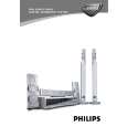
Hints for re-assembly of Top Cover Due to appearance design the Top cover (pos 252) is sandwiched between the Front panel (pos 101) and the 2 side covers (pos 102 & 103), this make it necessary to remove the 2 side covers before re-assembly of Top cover. 1) To remove the side cover use a small screw driver with marking 16mm from the tip end. 2) Insert the screw driver into slot (as shown in figure 2) and push the tip outwards to release the side cover catch. The side cover can be pull outwards as soon as the top catch is released.
C4
Turn up the lever, slide the bracket as shown and lift out of the bottom chassis.
Figure 4 Figure 5
Dismantling the Supply & Power Amplifier boards 1) Loosen 2 screws B mounting the Supply board's (pos 1102-B) heatsink to the Bottom Plate (pos 227) as per figure 6. Note: During re-assembly care must be taken to ensure the Mains Transformer wires to the Supply board is routed properly below the board. 2) Loosen 4 screws C to dismantle the Power Amplifier board (pos 1102-D) from the Bottom Plate as per figure 6. Figure 2 Figure 6
|
|
|
> |
|