|
|
|
Who's Online
There currently are 5713 guests online. |
|
Categories
|
|
Information
|
|
Featured Product
|
|
|
 |
|
|
There are currently no product reviews.
 ;
muy buen manual por lo completo de este algunos esquemas estan muy divididos lo que hace algo dificil el seguimiento.
;
very good manual, with detail and clarity in esquematic diagrams and waveforms .
 ;
Very quality copy of original service manual, which contains the circuit diagrams, PCB and lists of components, well as recommendation for calibration procedures of device, also everything else, that need for repair, tuning and use this oscilloscope.
All presented copies have high-resolution, so you can view all in detail.
This manual will very useful for simple owners and for repairers.
I recommend these manual, because myself is owner of Philips PM3216 and I need sometimes servicing these oscilloscope (principally calibrating).
Also, these document is an example of excellent design of technical documentation.
;
Excellent printing quality.
A complete and very usefull service manual with all details.
GREAT SERVICE AT VERY LOW PRICE!
A+++++++++++++++++++++++++
;
manual excelente completo , diagramas y esquemas bien presentados y buena calidad de imagen.
1-A. Preliminary/Final Checking and Alignment of Tape Path
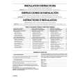
Purpose: To make sure that the tape path is well stabilized. Symptom of Misalignment: If the tape path is unstable, the tape will be damaged. Note: Do not use an Alignment Tape for this procedure. If the unit is not correctly aligned, the tape may be damaged. 1. Playback a blank cassette tape and check to see that the tape runs without creasing at Guide Rollers [2] and [3], and at points A and B on the lead surface. (Refer to Fig. M3 and M4.) 2. If creasing is apparent, align the height of the guide rollers by turning the top of Guide Rollers [2] and [3] with a Guide Roller Adj. Screwdriver. (Refer to Fig. M3 and M5.)
Guide Roller [2] Guide Roller [3]
3. Check to see that the tape runs without creasing at Take-up Guide Post [4] or without snaking between Guide Roller [3] and AC Head. (Fig. M3 and M5) 4. If creasing or snaking is apparent, adjust the Tilt Adj. Screw of the AC Head. (Fig. M6)
Azimuth Adj. Screw
AC Head X-Value Adj. Screwdriver
Tilt Adj. Screw
Fig. M6
1-B. X Value Alignment
Purpose: To align the Horizontal Position of the Audio/Control/ Erase Head. Symptom of Misalignment: If the Horizontal Position of the Audio/Control/Erase Head is not properly aligned, maximum envelope cannot be obtained at the Neutral position of the Tracking Control Circuit. Fig. M3 1. Connect the oscilloscope to TP301 (C-PB) and TP503 (CTL) on the Main CBA. Use TP504 (RFSW) as a trigger. 2. Playback the Gray Scale of the Alignment Tape (FL6NS8) and confirm that the PB FM signal is present. 3. Set the Tracking Control Circuit to the center position by pressing "VCR" button and "KCH" button on the remote control unit then pressing "PLAY" button on the unit. (Refer to note on bottom of page 2-3-4.) 4. Use the X-Value Adj. Screwdriver so that the PB FM signal at TP301 (C-PB) is maximum. (Fig. M6) 5. Press "KCH" button on the remote control unit until the CTL waveform has shifted by approx. +2msec. Make sure that the envelope is simply attenuated (shrinks in height) during this process so that you will know the envelope has been at its peak.
ACE Head
A
B Take-up Guide Post [4]
Lead Surface of Cylinder
Tape
Fig. M4
Correct
Guide Roller Tape
Incorrect
Take-up Guide Post Tape
Fig. M5 2-3-3 E9015MA
|
|
|
> |
|