|
|
|
Who's Online
There currently are 5908 guests online. |
|
Categories
|
|
Information
|
|
Featured Product
|
|
|
 |
|
|
There are currently no product reviews.
 ;
The purchased manual is an high quality scan of the original Philips paper-based Service Manual. I am very satisfied!
 ;
The purchased manual is an scan of the original Panasonic paper-based Service Manual. Unfortunately the contrast is not perfect, but I am satisfied anyway!
;
The purchased manual is an high-quality scan of the original JVC paper-based Service Manual. The Service Manual includes the Owner´s Manual, so you do not have to buy both of them.
;
It paid to find this Service Manual, couldn't find it anywhere else. Exactly what I wanted. Received within 24 hours.
;
Complete manual with clear schematic diagrams and printed circuit board layouts of two variants of the headset and the transmitter an old and a new version.
Also shows how the headset and the transmitter is opened and how transmitter and receivers can be adjusted and where to measure.
I had no problems to repair the headset using this service manual.
2-1
2-1
DISMANTLING INSTRUCTIONS
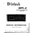
Dismantling of the Front Panel assembly 1) Loosen the 9 screws to dismantle the Top Cover (pos 252) - 2 screws on each side - 5 screws on the Rear Panel (pos 251). 2) Loosen 5 screws A and 8 catches C1 to slide the Front Panel assembly (pos 101, 102, 103, etc) as per figure 1. Note: To remove the Source / Volume control pc board (pos 1105B) 2 nuts hidden below the control knob assembly (pos 133, 134 and 135) must first be removed. 3) Loosen bracket (pos 254) by turning a catch, sliding towards the outside and lifting it upwards as per figure 5. Dismantling the Tuner, Mains and AV boards 1) Loosen 3 screws D and 2 catches C2 on the Rear panel (pos 251) to remove the Tuner board assemby (pos 1101) as pe figure 3. 2) Loosen 1 screws E and 2 catches C3 to unslot the Mains board (pos 1102-A) out of the Rear panel as per figure 4. 4) Loosen 7 screws F and 2 C5 to separate Rear Plate assembly (pos 251 + 227) from the Bottom plate as per figure 3. 5) Uncatch C4 to remove the AV board (pos 1104) from the Bottom & Rear Plate assembly (pos 251 + 227) as per figure 5.
C1
C1
C1
C1
A A
C1
A
C1
A
C1
Figure 1
A
C1
Figure 3
2 1 Turn up the lever, slide the bracket as shown and lift out of the bottom chassis.
Hints for re-assembly of Top Cover Due to appearance design the Top cover (pos 252) is sandwiched between the Front panel (pos 101) and the 2 side covers (pos 102 & 103), this make it necessary to remove the 2 side covers before re-assembly of Top cover. 2) Insert the screw driver into slot (as shown in figure 2) and push the tip outwards to release the side cover catch. The side cover can be pull outwards as soon as the top catch is released. Dismantling the 5DTC Module 1) Loosen 1 screws E and 2 catches C3 to remove the Mains board as per figure 4. 2) Loosen bracket (pos 254) by turning a catch, sliding towards the outside and lifting it upwards as per figure 5. 3) Loosen 3 screws G, lift up the 5DTC Module's (pos 1103A) rear and pull the module out towards the rear as per figure 6. Figure 4 1) To remove the side cover use a small screw driver with marking 16mm from the tip end.
C4
Figure 5
G G
Figure 2 Figure 6
|
|
|
> |
|