|
|
|
Who's Online
There currently are 5965 guests and
2 members online. |
|
Categories
|
|
Information
|
|
Featured Product
|
|
|
 |
|
|
There are currently no product reviews.
 ;
I found this manual to be complete in every detail. Besides the schematic it has a complete set of alignment instructions which are easy to understand. It also includes a complete parts list as well as an explanation of how the power supply and safety shutdown circuits operate. Even a schematic of the tuner is included.
 ;
The product was good and just what I needed, however I had moderate difficulty with the down load because the sight would not recognize my pass word. I was finally given a direct link to the manual and that worked.
;
Very quick and easy website to use and fast download of manual, quality of manual is excellent and will be pleased to use this service again in the future, thanks so much!
;
It is an very good and clear scanned service manual.
very recommended.
;
Easy to order the manual. Good quality and fast delivery.
3-1
3-1
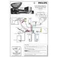
DISASSEMBLY INSTRUCTIONS
Dismantling of the Front Panel Assembly
1) Open the DVD Tray by using the Open/Close Button while the Set is ON and disconnect the mains supply after removing the Tray Cover.
Dismantling of the DVD Module
1) Loosen 4 screws "A" to remove the DVD Module as shown in figure 4. 2) Return the set to its upright position and remove the Tray Cover as shown in Figure 3 and close the tray manually by pushing it back in. 3) Loosen 9 screws and remove the Top Cover by lifting the rear portion upwards before sliding it out towards the rear. - 5 screws on the back - 2 screws each on the left & right side 4) Loosen 7 screws & lift up the top edge of Front Panel assembly to free some catches before sliding it out towards the front. - 4 screws on the bottom - 1 screw "E" on the inside as indicated in Figure 8. - 1 screw each on the left & right side
Note: If this is not possible, the DVD Tray has to be open manually.
Take a mini screw driver about 2mm diameter and make a marking 24mm from the tip as shown in figure 2. place the set on its side, insert the mini screw driver till the marking and slide it towards the right as shown in figure 1 until the Tray moves out of the Front Panel.
2mm
A
Repeat
Marking just outside the slot on the rear cabinet
Figure 4
Dismantling of the Power Board 1) Loosen 2 screws "B" on the bottom cover as shown in figure 5.
Figure 1
3) Loosen 4 screws "C" at the top of the Power Board as shown in figure 6
24mm
Figure 2
C
B
Figure 3
Figure 5
Figure 6
|
|
|
> |
|