|
|
|
Who's Online
There currently are 6040 guests online. |
|
Categories
|
|
Information
|
|
Featured Product
|
|
|
 |
|
|
There are currently no product reviews.
 ;
This manual was very good & was very helpful with repairs.
Always great & fast service from Owner's manual.
;
Very pleased with the quality of the scan. No complaints whatsoever.
 ;
I liked the product. I would use their sevices again.
;
I Recently purchased yet another Service Manual from Owner-Manuals.com, this time for a Sony EVS700ES/UB Videocassette Recorder. The Manual was available for upload within two hours and is an Extremely Good copy, as some of this I was able to enlarge to get even better detail.
Once Again, Very happy with the result!
;
A good and useful manual. With these, We was abled to isolate and pin point the component that was causing the problem. The total time spent in troubleshooting is very much reduced.
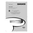
5. To shift the CTL waveform, press CH UP or CH DOWN button on the remote control unit. Then make sure that the maximum output position of PB FM envelope signal become within ±2ms from preset position.
4. If the envelope is as shown in Fig. M8, adjust the height of Guide Roller [3] (Refer to Fig. M3) so that the waveform looks like the one shown in Fig. M9. 5. When Guide Rollers [2] and [3] (Refer to Fig. M3) are aligned properly, there is no envelope drop either at the beginning or end of track as shown in Fig. M9.
Good
Preset position 2ms
Maximum output position of PB FM envelope signal FM envelope signal
Dropping envelope level at the beginning of track.
FM envelope output signal is adjusted at maximum.
CTL signal
Fig. M8
No Good
Dropping envelope level at the end of track.
FM envelope output signal is low.
Fig. M7
6. Set the Tracking Control Circuit to the preset position by pressing CH UP button on the remote control unit. and then �PLAY� button.
Fig. M9
1-C. Checking/Adjustment of Envelope Waveform
Purpose: To achieve a satisfactory picture, adjust the PB FM envelope becomes as flat as possible. Symptom of Misalignment: If the envelope output is poor, noise will appear in the picture. The tracking will then lose precision and the playback picture will be distorted by any slight variation of the Tracking Control Circuit. 1. Connect the oscilloscope to TP (C-PB) on the Main CBA. Use TP (RF-SW) as a trigger. 2. Playback the Gray Scale on the Alignment Tape (VFMS0001H6). Set the Tracking Control Circuit to the preset position by pressing CH UP button and then �PLAY� button on the unit. Adjust the height of Guide Rollers [2] and [3] (Fig. M3, Page 2-3-3) watching the oscilloscope display so that the envelope becomes as flat as possible. To do this adjustment, turn the top of the Guide Roller with the Guide Roller Adj. Screwdriver. 3. If the envelope is as shown in Fig. M7, adjust the height of Guide Roller [2] (Refer to Fig. M3) so that the waveform looks like the one shown in Fig. M9.
Envelope is adjusted properly. (No envelope drop)
Fig. M10
Note: Upon completion of the adjustment of Guide Rollers [2] and [3] (Refer to Fig. M3), check the X Value by pushing the CH UP or DOWN buttons alternately, to check the symmetry of the envelope. Check the number of pushes to ensure preset position. The number of pushes CH UP button to achieve 1/2 level of envelope should match the number of pushes CH DOWN button from center. If required, redo the �X Value Alignment.�
2-3-4
U29NMA_PC
|
|
|
> |
|