Super Anleitung. Ordentliche Auflösung. Das ganze noch in Deutsch wäre zu schön. Alle Datenblätter sind sauber Kopiert und alle Leitungswege sind sauber ausgeführt
About the service it's very fast and reliable. About the manual the quality is high enough to read even the tiniest details on the wiring diagrams so you can't ask much more than that, let it alone for a manual of a product from 20 years ago. Thank you, very satisfied.
The downloaded quality was as good as the orignial
Text excerpt from page 6 (click to view)
4-2
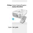
LC6231/LC7181
5. Remove the 6 screws �F� holding the top shield (Fig. 5). Then remove the 3 screws �G� and the 2 screws �H� (Fig. 6). Now the top shield can be removed. 2. Remove screw �K� and connectors �L� (Fig. 8). Nor the DRB (Drive Boards) can be removed.
DRB Board
F F F
F
F
F
CL 266450004_049.eps 240402
K
L
CL 266450004_052.eps 240402
Fig. 5
Fig. 8
H
H
3.
Remove screw �L� (Fig. 9). Now the bottom shield can be removed.
L
G
G
G
CL 266450004_050.eps 24402
Fig. 6 4.2 Panel removal and service position 1.
Bottom Shield
Remove screw �I� and connectors �J� (Fig. 7). Now the SSB (Small Signal Board) can be removed. The SSB is plugged onto the DRB (Drive Board).
DRB Board