|
|
|
Who's Online
There currently are 6002 guests online. |
|
Categories
|
|
Information
|
|
Featured Product
|
|
|
 |
|
|
There are currently no product reviews.
 ;
Great service. Fast response. High quality scan. Good price.
Thank you very much!!!
Oleg S.
;
Well-scanned, complete manual. Contains the information needed for repair and maintenance.
;
It's great to be able to obtain a precious technical information for a real old equipment. The one I got helps me a lot in the area of wiring diagram to repair my antique. PDF gave me clear enough information to find out thr details. Thanks for giving me the oppotunity to be able to access to almost vanished informations.
;
Another excellent aquisition. Fine detailed manual. Thanks
 ;
Good quality for the scan, complete, but as usual for Tascam, not so comprehensive !
EN 24
4.
EM5E
Mechanical Instructions 4.5 Set Reassembly
To reassemble the whole set, do all processes in reverse order. Be sure that, before the rear cover is mounted: � The mains cord is mounted correctly in its guiding brackets. � All wires/cables are returned in their original positions. This is very important due to the large 'hot' area of the set
1. Release the two fixation clamps (rather difficult to reach), by pushing them upwards [1]. At the same time, pull the complete assy backwards [2]. Note: be aware that the degaussing coil can hamper this. 2. Release the two fixation clamps on the two sides of the bracket (the board hinges at the connector side). 3. Remove the board from the bracket. 4. When the light guide (sitting in the cabinet, in front of the LEDs) is defective, you can replace it by pushing it forwards at the left side (it hinges at the right side, seen from the rear). 4.4.4 DAF Assy/Panel
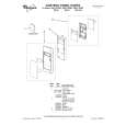
1 4 3 3
4
2
CL 16532044_011.eps 150501
Figure 4-11 DAF-module
1. Remove the fixation screw [1] (if present). 2. Push down the fixation clamp [2], and pull the complete bracket at the same time away from the CRT [3]. The module is now free from the LSP-bracket. 3. Release the fixation clamps [4], in order to remove the print from its bracket. 4.4.5 Auto-SCAVEM Assy/Panel This panel is placed on the left side of the SSB (See figure �Service position 2�). Because most of its components are placed on the bottom side, you must lift the panel from its bracket before you can measure it. 1. Therefore, release the two fixation clamps at the top. 2. Lift the panel from the bracket (it hinges at the bottom). To remove the bracket: 1. First, remove the panel from the bracket, as described above. 2. Then, remove the two fixation screws at the bottom. 3. Lift the Auto-Scavem bracket slightly up, and at the same time bend the top a little away from the tuner. 4. Now, push the bracket into the direction of the CRT, and lift it out of the LSP-bracket. 4.4.6 Small Signal Board (SSB) See paragraph 'Small Signal Board (SSB)' above. 4.4.7 Large Signal Panel (LSP) 1. Remove the SSB (see paragraph 'Small Signal Board (SSB)' above). 2. Remove the Auto-Scavem assy (see paragraph 'Auto Scavem Assy/Panel' above). 3. Disconnect the necessary cables. 4. Release the fixation clamps on the left of the LSP-bracket (the board hinges at the right side). 5. Remove the board from the bracket.
|
|
|
> |
|