|
|
|
Who's Online
There currently are 5686 guests online. |
|
Categories
|
|
Information
|
|
Featured Product
|
|
|
 |
|
|
There are currently no product reviews.
 ;
Very fast service, best quality of the service manual and the schematics
 ;
This service manual of the old video cassette recorder VT-LC50EM is very good readable even the tiniest numbers (i.e. IC-pins). The circuits are very clear. Many details of the schematic are very good described but in GERMAN language. Many schematic details - but complete at all. Common background information of several details are enclosed and physical knowledge of the TFT liquid crystal display for example. The manual lacks PCB drawings. If you understand german I would recommend this manual for you.
;
Hi, this is a very clear manual, nice copy, not quite up to the standard of the very best available but better than many others. I think the price was especially fair for a hard to find manual and I would certainly use this manual seller again. Recommended.
;
This schema available for me in good condition. I would highly recommend.
;
Thanks for this "hard to find" service manual.
I apreciate the good quality of scanning and the pages scanned in A3 format.
Service Modes, Error Codes and Fault Finding
diagram A6) will put the IC7700 in Standby mode (via tristate input pin 6). For more details, see chapter 9.
EM5E
5.
EN 33
5.8
5.8.1
Repair tips
Miscellaneous The relay you hear when you switch the set 'on' (from Standby or via the mains switch), is from the degaussing circuitry. It is not used for switching the Power Supply (as done in the MGchassis). Take care not to touch the �hot� heatsink while disconnecting the SSB, despite the fact that the mains cord is out of the mains socket. There can still be an annoying rest-voltage on the heatsink for a short while. This, because the discharge resistors 3502 and 3503 (on the LSP between hot and cold part) are not stuffed for Europe. Instead, discharge resistors 3066 and 3057 on the Mains Switch panel are used, but because they are located before the Mains switch, they only discharge when this switch is �on�. Advice: when you remove the SSB, disconnect the Mains cord, but keep the Mains Switch �on�. Do not try to measure on the SSB side, which is facing the �hot� heatsink. This is dangerous. Most service test points are guided to the �tuner� side and are indicated by the �service� printing. Where the circuitry was too �crowded� for this printing, you can find the correct location on the �test point overviews� in this manual (chapter 6). A very large part of the LSP is 'hot', such as: � The primary part of the Standby Supply. � The whole Main supply (except for the secondary Audio supply). � And the complete deflection circuitry (so notice that the deflection coil is hot!!). 5.8.4
3. Via the �SUP-ENABLE� signal, the Main Supply is switched �on� and will deliver the VBAT to the Line deflection stage [2]. 4. EHT generation is now started. 5. The OTC will un-blank the picture. 6. When you switch �off� the set, this is done in a controlled way via the POR signal [3]. Note: Standby is not directly achieved via the Standby line of the microprocessor, but indirectly via the HOP circuitry. 5.8.3 ComPair This chassis does not have an IR transmitting LED (as in MGsets). Therefore, a �Service� (ComPair) connector is implemented at the rear side of the set, which is directly accessible (as in A10-, EM2E- and EM3E-sets). In addition to this, there is also a blinking LED procedure to show the contents of the error buffer. When you use ComPair, you have the possibility to activate a �stepwise start-up� mode. With this mode, you can initiate the start-up sequence step by step. This also means that in certain steps, some protections are not activated. This is sometimes very convenient during repair (see also paragraph 5.4.3). Protections There are �service pads� implemented on the SSB (items 9005 and 9006, outside the shielding), to force the set in SAM or SDM (see also figure: �SSB removal (part 3)� in Chapter 4). This will overrule the processor-controlled protections, but not the hardware protections. This means, that the A/D-input protections (5 and 8 V) and the I2C �not-acknowledging� info of the feature box (FBX) and of the Tuner are overruled. Caution: When doing this, the service technician must know what he is doing, as it could lead to damaging the set. The �ARC�- and/or �BRIDGECOIL� protection are hardly ever triggered, however: When you suspect the �ARC� protection, look for bad solder joints and smell. By interrupting resistor 3497, this protection is disabled (special attention needed!). When you suspect the �BRIDGECOIL� protection, which can also be due to a too wide picture amplitude, shorten G and S of the E/W MOSFET 7480. This will disable the protection. You will now have minimal horizontal amplitude. Re-align the horizontal amplitude in the SAM menu and remove the G/S
5.8.2
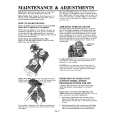
Start-up Sequence
COLD HOT
EHT-INFO
8V 2 I C BUS 1
5 START/STOP 17/39 HOP 29 START/STOP OUT
5VCON RESET 106 8VCON 105 OTC 99 POR STANDBY low 7131/41 closed high 7131/41 open 3 7131 104 7141 5V 8V
CUTOFF (from CRT panel) 2
short of TS7480. 5.8.5
220 VAC
Main Supply The simplest way is, to replace the components of the Main Supply with repair kit (3122 785 90310) More detailed way: 1. Replace FET 7504 and zener 6505. 2. Remove the SSB panel. 3. Short B and E of TS7529, in order to put the Main Supply in �on�-mode (TS7529 is blocking then). Caution: To prevent that R3403 and TS7443 will be damaged, first disable the HW-protection of the deflection circuit. Therefore short circuit C2642 on the LSP (diagram A4). 4. Attach a load of 500 � to VBAT capacitor C2515 (the supply can not work without a minimum load). 5. Use a variac, and slowly increase the VMAINS. Measure over sensing resistors R3514//15 if a nice sawtooth voltage becomes available. 6. Also measure the VBAT. This may never exceed +141 V. If it does, there is something wrong in the feedback circuitry (e.g. regulator 7506). Note: Be careful when measuring on the gate of FET TS7504. This circuitry is very high ohmic and can easily be damaged
STBY SUPPLY
MAIN SUPPLY
Vbat
SUP-ENABLE
+11D POR 7445
LINE DEFL. (BRIDGECOIL -PROT) (ARC-PROT) PROTSENSING FRAME DEFL (NON-VFB)
CL16532044_023.eps 140501
Figure 5-3 Start-up circuitry The start up sequence differs from other sets (e.g. MG-sets or EM2E-sets, but is same as in EM3E-set): 1. When the set is switched �on�, the 5 and 8 V lines (�+5V_CON� and �+8V_CON�) of the standby power supply are activated. 2. After the OTC senses them, the µP will address the HOP via the I2C-bus, to start the drive [1].
|
|
|
> |
|