|
|
|
Who's Online
There currently are 6043 guests online. |
|
Categories
|
|
Information
|
|
Featured Product
|
|
|
 |
|
|
There are currently no product reviews.
 ;
Good service manual,i saved from scrapping this deck,is now fully functional.Thanks.
 ;
Found this to be the manual included with the original packinging, was helpfull but did not give any detailed repair instructions.
;
Complete service manual, was very helpful in repairing this tapedeck.Thanks.
;
The service manual was a copy of the original from Wirlpool. The quality was good, all neccecary information was available including the service-codenumbers, so I could order the right part to be replaced for repair.
Downloding was no probem after the payment.
Thanks for the service!
;
Good,readable manual. I found other manuals that were not readable when it came to part ID, but the one downloaded from owner-manual.com was better than expected. I will do buisness with owner-manual.com again.
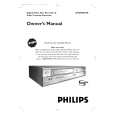
5. To shift the CTL waveform, press CH UP or CH DOWN button on the remote control unit. Then make sure that the maximum output position of PB FM envelope signal become within ±2ms from preset position.
4. If the envelope is as shown in Fig. M8, adjust the height of Guide Roller [3] (Refer to Fig. M3) so that the waveform looks like the one shown in Fig. M9. 5. When Guide Rollers [2] and [3] (Refer to Fig. M3) are aligned properly, there is no envelope drop either at the beginning or end of track as shown in Fig. M9.
Good
Preset position 2ms
Maximum output position of PB FM envelope signal FM envelope signal
Dropping envelope level at the beginning of track.
FM envelope output signal is adjusted at maximum.
CTL signal
Fig. M8
No Good
Dropping envelope level at the end of track.
FM envelope output signal is low.
Fig. M7
6. Set the Tracking Control Circuit to the preset position by pressing CH UP button on the remote control unit. and then �PLAY� button.
Fig. M9
1-C. Checking/Adjustment of Envelope Waveform
Purpose: To achieve a satisfactory picture, adjust the PB FM envelope becomes as flat as possible. Symptom of Misalignment: If the envelope output is poor, noise will appear in the picture. The tracking will then lose precision and the playback picture will be distorted by any slight variation of the Tracking Control Circuit. 1. Connect the oscilloscope to TP (C-PB) on the Main CBA. Use TP (RF-SW) as a trigger. 2. Playback the Gray Scale on the Alignment Tape (VFMS0001H6). Set the Tracking Control Circuit to the preset position by pressing CH UP button and then �PLAY� button on the unit. Adjust the height of Guide Rollers [2] and [3] (Fig. M3, Page 2-3-3) watching the oscilloscope display so that the envelope becomes as flat as possible. To do this adjustment, turn the top of the Guide Roller with the Guide Roller Adj. Screwdriver. 3. If the envelope is as shown in Fig. M7, adjust the height of Guide Roller [2] (Refer to Fig. M3) so that the waveform looks like the one shown in Fig. M9.
Envelope is adjusted properly. (No envelope drop)
Fig. M10
Note: Upon completion of the adjustment of Guide Rollers [2] and [3] (Refer to Fig. M3), check the X Value by pushing the CH UP or DOWN buttons alternately, to check the symmetry of the envelope. Check the number of pushes to ensure preset position. The number of pushes CH UP button to achieve 1/2 level of envelope should match the number of pushes CH DOWN button from center. If required, redo the �X Value Alignment.�
2-3-4
U29NMA_PC
|
|
|
> |
|