|
|
|
Who's Online
There currently are 6043 guests online. |
|
Categories
|
|
Information
|
|
Featured Product
|
|
|
 |
|
|
There are currently no product reviews.
 ;
Great manual very clear copied. You are making an incredible job. I appreciate a lot the rapidity and your efficiency. Thanks a lot
;
Good pdf of the service manual for this unit. Includes disassembly instructions, full schematics, board layouts, parts lists and diagnostic information. Some information is in the pdf twice (single pages, and split pages), but that could be how it was originally generated by panasonic, or perhaps the idea is to make it eaiser to put onto 8.5 x 11" pages.
Information was exactly what I needed. Delivery was overnight (less than 12 hours) and I was happy with the process.
;
5 STARS for FAST DELIVERY, BEST PRICES and QUALITY PRODUCT. Item was exactly as described with superb resolution. Will definitely source all my future requirements from this website. Thanks a lot owner-manual.com!
;
OEM manual provided all schematics, board layouts and component specs necessary to facilitate unit maintenance. All pages were clear and readable.
;
Good condition and quality. Hard to find anywhere in Internet, only on this site.
6
104S CM23 GSIII Go to cover page
Mechanical Instructions
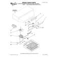
0. General To be able to perform measurements and repairs on the "circuit boards", these unit should placed in the service position first. 1. Remove the rear cover - Open two lids with "-" type screwdriver. Refer to fig2 and fig3. - Remove 4 screws with "+" type screwdriver. 2. Video panel - Remove the metal shielding on rear side of Video panel by desolder lags of metal shielding. 3. Main panel - Disconnect the degaussing coil from Main panel. - Remove the video panel from CRT. - Remove the "screw" of I/F cable from Main panel. - Disconnect the CRT ground "1701" from Video panel. - Disconnect the Hi-Pot cap from CRT. - Disconnect the yoke wire connector "1601" from Main panel. - Slide the main panel out of bottom tray. - Place Main panel in service position as shown in Fig.1. - Mount Video panel again on CRT. - To connect Hi-Pot cap again. - To connect "1701" again. - To connect the yoke wire "1601" again.
lids
lid
Fig.2
screws
screws
Fig. 1
Fig.3
Back
Forward
|
|
|
> |
|