|
|
|
Who's Online
There currently are 6007 guests online. |
|
Categories
|
|
Information
|
|
Featured Product
|
|
|
 |
|
|
There are currently no product reviews.
 ;
Sweet! I won the item on eBay and couldn't adjust the geometry or even keep a steady picure. This guide has the full schematics (not available anywhere else as far as I could tell), and was a bargain for the wealth of knowledge it contains. I hooked it up to my testing equipment, tweaked a few potentiometers and got it playing videogames in no time. Thanks!
;
It was just what I need to fix my old BMW's CD player. Very convenient also. Thank you.
;
Great Manual! It contains all the wiring schematics and mechanical exploded views that are essential for service and repair. I was surprised I even found this for such an old machine. Only wish I knew of this site many years ago.
;
Great manual very clear copied. You are making an incredible job. I appreciate a lot the rapidity and your efficiency. Thanks a lot
;
Good pdf of the service manual for this unit. Includes disassembly instructions, full schematics, board layouts, parts lists and diagnostic information. Some information is in the pdf twice (single pages, and split pages), but that could be how it was originally generated by panasonic, or perhaps the idea is to make it eaiser to put onto 8.5 x 11" pages.
Information was exactly what I needed. Delivery was overnight (less than 12 hours) and I was happy with the process.
6
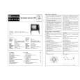
104S CM23 GSIII Go to cover page
Mechanical Instructions
0. General To be able to perform measurements and repairs on the "circuit boards", these unit should placed in the service position first. 1. Remove the rear cover - Open two lids with "-" type screwdriver. Refer to fig2 and fig3. - Remove 4 screws with "+" type screwdriver. 2. Video panel - Remove the metal shielding on rear side of Video panel by desolder lags of metal shielding. 3. Main panel - Disconnect the degaussing coil from Main panel. - Remove the video panel from CRT. - Remove the "screw" of I/F cable from Main panel. - Disconnect the CRT ground "1701" from Video panel. - Disconnect the Hi-Pot cap from CRT. - Disconnect the yoke wire connector "1601" from Main panel. - Slide the main panel out of bottom tray. - Place Main panel in service position as shown in Fig.1. - Mount Video panel again on CRT. - To connect Hi-Pot cap again. - To connect "1701" again. - To connect the yoke wire "1601" again.
lids
lid
Fig.2
screws
screws
Fig. 1
Fig.3
Back
Forward
|
|
|
> |
|