|
|
|
Who's Online
There currently are 6040 guests online. |
|
Categories
|
|
Information
|
|
Featured Product
|
|
|
 |
|
|
There are currently no product reviews.
 ;
I PURHASED THIS PRODUCT BECAUSE I WAS HAVING PROBLEMS WITH MY CDR20 HARMAN KARDON RECORDER. WHICH I PURCHASED NEW 12 YEARS AGO. AFTER REVIEWING THE MANUAL, I WAS ABLE TO ADJUST THE TENSIONER IN THE SYSTEM. WORKS LIKE A CHAMP!.
SAVED ME AT LEAST 100.00 WHICH WAS WHAT A SERVICE REPAIR STATION WANTED. GREAT MANUAL EASY TO READ. SPECIALLY AFTER I PRINTED THE PAGES WHICH DEALT WITH MY RECORDER. THANKS A LOT!!!!!!!!
 ;
You can fully trust on this one!
All the schematics are very crear an in one piece per page
;
I have never bought a service manual which is as competely readable as this althogh it was a scanned pdf. Thank you for this succesful manual also cheaper than other sites.
;
Thanks for a very good and readable servicemanual. Just what I needed as a "dinosaur technician". I really recommmend this site and will come back.
Åsbjörn
;
The manual I purchased was just what I needed. I was glad to find a site where I can find so many manuals on a wide variety of products.
GB 60
8.
CDR779
Faultfinding Guide
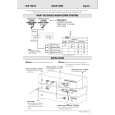
becomes reversed. This results in a current flow through the tranformer�s secondary winding via the diodes, electrolytic capacitors and the load. This current is also ramp shaped but decreasing. TimeDEAD phase : when the stored energy has been supplied to the load, the voltage from the secondary windings falls below the output voltage(held constant by the electrolytic capacitors) plus the threshold voltage of the diodes. The current in the secondary winding stops flowing. At this point, the drain voltage of the MOSFET is not yet zero because C2609 between drain and source contains a certain charge. This charge will start a sine-shaped ringing together with the transformer�s self-induction. The oscillator will start a next cyclus which consists of the described three phases. The time of the different phases depends on the mains voltage and the load. TimeDEAD is maximum at an input of 400VDC and minimum load, it will be zero at an input of 100VDC and overload.
V2 Vosc
capacitor at the Vcc pin will discharge because the primairy auxiliary voltage, coming from winding7-9 is below the Vcc voltage. At some moment during t2, the primary auxiliary voltages reaches the same level as Vcc. This primary auxiliary voltage now determines the Vcc voltage t3: regulation The output voltage of the power supply is in regulation t4: overload When the output is shortened, the supply voltage of the circuit will decrease and after some time drop below the lower threshold voltage. At that moment, the output will be disabled and the process of charging the Vcc capacitor starts again. If the output is still shorted at the next t2 phase, the complete start-and stop sequence will repeat. The power supply comes in a hiccup mode.
16V 12V 10V Vc2134 0V Vcc
V1 0
20mA Icc 1mA
Vcomp Vsense
Vgate
OUTPUT
Vdrain
short Vo 0 t1 t2 t3 t4
Idrain
Idiodes
Figure C : Start-up sequence
CL 06532151_020.eps 271100
Ton
Tdiode Tdead
CL 06532151_021.eps 271100
Figure 8-12 8.2.5 Regulation Figure 4 shows the most relevant signals during the regulation phase of the power supply. The oscillator voltage ramps up and down between V1 and V2. The voltage at the current sense terminal is compared every cycle with the output of the error amplifier Vcomp. The output is switched off when the current sense level exceeds the level at the output of the error amplifier. TimeON phase : A drain current will flow from the positive supply at pin 1 through the transformer�s primary winding, the MOSFET and Rsense to ground. As the positive voltage at pin 1 of the transformer is constant, the current will increase linearly and create a ramp dependent on the mains voltage and the inductance of the primary winding. A certain amount of energy is stored in the transformer in the form of a magnetic field. The polarity of the voltages at the secundary windings is such that the diodes are non-conducting. TimeDIODE phase : When the MOSFET is switched off, energy is no longer supplied to the tranformer. The inductance of the tranformer now tries to maintain the current which has been flowing through it at a constant level. The polarity of the voltage from the transformer therefore
Figure 8-13
 $4.99 CDR779 PHILIPS
Quick Start Quick start guide ( sometimes called quick guide ) contains most important information on how to use…
|
|
|
> |
|