I searched the Internet exhaustively for this manual and Owner-Manuals was the least expensive...but provided an excellent reproduction within 4 hours. Very satisified.
The delivery of this manual was very fast, less than 8 hours. The manual is very clear and concise, and helped a great deal in the repair and final setup of the Hitachi HMA-G2 Amplifier.
Text excerpt from page 6 (click to view)
2-1
SERVICE HINTS
REPAIR POSITION COPPERSIDE REPAIR POSITION COMPONENTSIDE
To get access to the copperside of the printed board assembly proceed as follows: 1. Remove the bottom screws (4x) 2. Remove the cabinet screws (4x) 3. Lift the bottom (take care of cabinet/bottom snaps) 4. Supply the unit via external DC-socket
To get access to the componentside of the printed board assembly proceed as follows: 1. Remove the bottom screws (4x) 2. Remove the cabinet screws (4x) 3. Lift the bottom (take care of cabinet/bottom snaps) 4. Lift the printed boards and flip the main board 5. Supply the unit via external DC-socket 6. Short-circuit door-switch 1409 during measurements
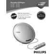
POSITIONING OF SPRING-OPEN
POSITIONING OF SPRING-CD-DOOR
ROUTING OF CD-DRIVE WIRES
Remark: The spring for the CD-door is positioned loose in the cabinet assembly as shown in the picture above. It will be caught in its defined position just after mounting cabinet and bottom parts together.