|
|
|
Who's Online
There currently are 5962 guests online. |
|
Categories
|
|
Information
|
|
Featured Product
|
|
|
 |
|
|
There are currently no product reviews.
 ;
I needed the manual immediately and I got it immediately. I couldn't find this manual anywhere else on the net. The site was easy to traverse, and the price was very reasonable. I'll definitely be back for any future needs.
 ;
I received a good service manual, with good resolution. Improve the instructions for the purchase because they are not well understood.
For the rest, so good.
Thanks Angel.
;
Very good documentation for the Grundig 2077 model (as well as similar 800/900/1000 series radios). The first two pages are a summary of reception specifications and output capability. The third page is the tuner dial indicator and dial cord routing diagram. the final ~5 pages are the schematics for the various models (including 2077). The scan quality of the schematics are good, adn can be easily read if zoomed in. The documents are in German, not English as stated. It would have been nice to have the tuning sequence and settings, and some trouble shooting materials... or component and wiring map.
;
Perfect like it was descriped, Perfect like it was descriped
;
Very good detail, all pages clear, exactly what I needed
GB 98
9.
EM3E
Circuit Descriptions and Abbreviation List
and transistor TS7502, TON of the FET is changed (will increase). The output voltage VBAT will rise. If the load continues to increase, the regulator will block at a certain moment. TON will is now at maximum value. This is the point where VBAT will go below 141 V and, at further increasing load, is switched �off� (the voltage across the cocoupled coil (4, 5) will decrease, due to the increasing load. Therefore the voltage on the gate of TS7504 comes below the threshold voltage. The supply switches �off� and an audible hiccuping can be heard).
5 5506 6536 6501 2513 -16V 2503 COLD 3504 Vbat 3520 33k 3506 7506 2515 3507 6535 2512 +16V
Implementation
V - MAINS
1503 2.5A
375V 3513
A
6510 15V 6530
Vbat 141V
3518
3511
D S
7504
G
3508 6505 15V 3522 3512 6515 5V6
7507
7530
7502
3514//15
B
On the other hand when the load decreases, VBAT will rise. As a consequence, the input voltage of TS7506 will also rise, resulting in a higher current. This changes the base voltage of TS7502, and through that the TON (will decrease) of the FET. The output voltage V will be reduced.
BAT
HOT
141V
CL 16532044_030.eps 160501
If, for instance, VIN will decrease (e.g. UMAINS is 180 V i.s.o. 240 V), the slope of the drain-current will be flattened, through which the FET will be longer into conductance, keeping VOUT constant. If, for any reason, the stabilisation circuit might fail, the output voltage VBAT can never exceed 200 V (via D6514). D6514 will form a short-circuit, VBAT will drop and the set will switch off (this will result in an audible hiccuping of the supply).
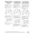
Figure 9-6 At start-up of the main supply, C2515 can be assumed as being a short-circuit. UAB will be 15 V (R3513, D6510) and UGS of the FET will be +5.4 V. The FET will be driven into saturation (same as closing switch 'S'). The drain-current will increase linear in time. With other words: resistors R3513 and R3518 will start the oscillator. The voltage across the co-coupled coil (4, 5) is also positive and will keep the FET into conductivity. The drive concept of the MOSFET TS7504 has changed (compared to the EM2E chassis). In EM2E, TS7502 was a high-voltage semiconductor, in EM3E it is changed to a lowvoltage semiconductor. The added opto-coupler 7505 is used to bridge the different voltage levels. Via this opto-coupler, the DC-current through R3504 is influenced. The changed current through R3504, changes the VBE of TS7502, which will influence the drive of MOSFET TS7504 (= switch �S� in Fig. 5). The sudden current interruption in the primary coil, will induce a counter-e.m.f. that wants to maintain the current via the 'freewheel'diode D6508. This current is linear decreasing in time and as it is also flowing through R3414//R3415, TS7502 will be blocked after a certain time period. The gate of the FET will be again made positive, is driven into conductivity and the cycle starts again. For safety reasons, transistor TS7530 is added as a back-up solution for TS7502. If B-E of TS7502 is shorted, TS7530 takes over its function.
Switch to �Standby� (via RC) When the set is switched to 'Standby' mode via the Remote Control, the Main supply is switched �off� by the circuit around TS7529 (see diagram A1). During 'on'-state, the Main supply is fed with line pulses via the �SUP-ENABLE� line. They are rectified and smoothed via D6517, D6516 and C2530 and fed to TS7529. Because they are less than -13 V, this transistor is blocked. When these pulses are stopped, TS7529 will be saturated and TS7502 will switch �off�. This will switch �off� the Main supply. Set to �On� (via �SUP-ENABLE�) Via the �STANDBY� command from the OTC, the MOSFETS 7141 and 7131 are switched �on�. When the +5V and +8V are sensed by the OTC, a command is given to the HOP to start the drive (via I2C). When this is sensed via the �SUP-ENABLE� line (at the base of line transistor TS7421), the main supply is switched �on� via TS7529. Audio Supply The pulses on the secondary winding of L5506 are rectified by D6535 (+16 V) and D6536 (-16V), and smoothed by C2542 and C2543.
Stabilisation of VBAT The output voltage VBAT is determined by: VBAT = VIN * TON / (TON + TOFF) = VIN * duty-cycle. To stabilise the output voltage, a feedback loop is implemented, which will reduce TON when VBAT increases and vice versa.
Via a voltage divider, excisting of (1 %) resistors R3507, R3510 and R3527, a voltage of 2.5 V (when VBAT = 141 V) is fed to the input of precision shunt regulator 7506. This regulator will conduct, a current will flow through the diode part of the opto-coupler 7507. The base of TS7502 will now be set at a certain positive voltage. As this transistor switches the FET TS7504 on and off, this circuit can determine the duty-cycle. E.g. when the load increases, VBAT will decrease. As a consequence, the input voltage of regulator 7506 will decrease, resulting in a lower current. Via opto-coupler 7505
|
|
|
> |
|