|
|
|
Who's Online
There currently are 5770 guests online. |
|
Categories
|
|
Information
|
|
Featured Product
|
|
|
 |
|
|
There are currently no product reviews.
 ;
This service manual includes drawings, schematics, exploded views, parts list, operating details, and more. Very good scans, very readable. The only thing that made it a 4 star rating was on approximately 4 scans only half of the page was scanned then the other half. I would have preferred the pages to be whole scans.
 ;
Good manual contains all it takes to update, repair,these types of mixers.Thanks.
;
Great service. Fast response. High quality scan. Good price.
Thank you very much!!!
Oleg S.
;
Well-scanned, complete manual. Contains the information needed for repair and maintenance.
;
It's great to be able to obtain a precious technical information for a real old equipment. The one I got helps me a lot in the area of wiring diagram to repair my antique. PDF gave me clear enough information to find out thr details. Thanks for giving me the oppotunity to be able to access to almost vanished informations.
1-2
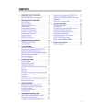
TABLE OF CONTENTS
Page Front page .............................................................................. 1-1 Table of contents ................................................................... 1-2 Survey of sets and features ................................................... 1-3 Survey of sets and boards ..................................................... 1-4
V. EXPLODED VIEWS AND PARTS LISTS
Mechanical parts list .............................................................. 5-1 Electrical parts list .................................................................. 5-4
III. SCHEMATICS
Interconnection wiring diagram .............................................. 3-1 Block diagram - Tuner1, TV ................................................... 3-2 Block diagram - Power Supply, Large Signal,TXT ................ 3-3 Block diagram - In/Out, Audio ................................................ 3-4 Block diagram - Tuner2, Video .............................................. 3-5 Block diagram - Central Control, Deck Electronics ............... 3-6 TV Board (TVB) Power Supply (PS) - Schematic diagram .............................. 3-7 Deflection (LS) - Schematic diagram ..................................... 3-8 Tuner 1 (TU1) - Schematic diagram ...................................... 3-9 TV Processing (TV) - Schematic diagram ........................... 3-10 Input/Output (IO_1) - Schematic diagram ........................... 3-11 View Selector Audio (SF) - Schematic diagram .................. 3-12 Amplifier (AMP) - Schematic diagram ................................. 3-13 Teletext Controller (COTV) - Schematic diagram ................ 3-14 Recorder Unit Board (RUB) Power Supply (PS) - Schematic diagram ............................ 3-15 Central Control 1 (AIO1) - Schematic diagram .................... 3-16 Central Control 2 (AIO2) - Schematic diagram .................... 3-17 Deck Electronics (DE) - Schematic diagram ....................... 3-18 Clock, VPS, Buzzer (CVB) - Schematic diagram ................ 3-19 Tuner 2 (TU2) - Schematic diagram .................................... 3-20 Sound Processing (AP) - Schematic diagram ..................... 3-21 FM-Audio Processing (AF) - Schematic diagram ................ 3-22 Linear Audio Processing (AL) - Schematic diagram ............ 3-23 Video Signal Processing (VS) - Schematic diagram ........... 3-24 SECAM Processing (VSEC) - Schematic diagram ............. 3-25 Head Amplifier (HA) - Schematic diagram .......................... 3-26 Headphone, Front-AV Board (HPAV) Schematic diagram .............................................................. 3-27 CRT-Board (PT) Schematic diagram .............................................................. 3-28 Audio Board (APDOD) Pre Amplifier (ACO) - Schematic diagram ........................... 3-29 Audio Processing (AF2) - Schematic diagram .................... 3-30 Sound Feature Board (SFD) Schematic diagram .............................................................. 3-31 Cinch Out, Scart 2 Board (DOSCD) Schematic diagram .............................................................. 3-32 Keys & Display Board (KB1D) Schematic diagram .............................................................. 3-33 Key Board (KB2D) Schematic diagram .............................................................. 3-34 Mainsfilter Board (MFSWD) Schematic diagram .............................................................. 3-34 Variant list Tuner 1 - TV Board (TVBAD) .............................................. 3-35 Tuner 2- Recorder Unit Board (RUBAD) ............................. 3-36
IV. CIRCUIT BOARD DIAGRAMS
Sound Feature Board (SFD) .................................................. 4-1 Mainsfilter Board (MFSWD) ................................................... 4-1 Audio Board (APDOD) ............................................................ 4-1 TV Board (TVBCD), CRT Board, HPAV Board, Switch Board .. Components side .................................................................... 4-2 Copper side ............................................................................ 4-5 TV Board (TVBDD), CRT Board, HPAV Board, Switch Board .. Components side .................................................................... 4-6 Copper side ............................................................................ 4-9 Recorder Unit Board (RUB2D) Components side ................................................................. 4-10 Copper side .......................................................................... 4-11 Cinch Out, Scart 2 Board (DOSCD) .................................... 4-12 Keys & Display Board (KB1D, KB2D) ................................ 4-12
|
|
|
> |
|