|
|
|
Who's Online
There currently are 5901 guests online. |
|
Categories
|
|
Information
|
|
Featured Product
|
|
|
 |
|
|
There are currently no product reviews.
 ;
Complete service manual in very good scanning quality with all schematic and PWB graphics as well as assembly & maintenance instructions. A slight drawback is that the rastering of the PWB graphics sometimes makes it a bit difficult to follow fine traces, but no showstopper.
;
Purchased the manual that I was looking for at a great price and could download it easily.. Great service experience and for future purchases I plan to use the site. Thank you very much
 ;
Service manual in good quality, it was very helpful to me. Perfect service, I am very satisfied.
Jochen Kelm
;
Exellent manual ,it was in great condition,and got all the info i expected,5 stars!!
;
I searched the Internet exhaustively for this manual and Owner-Manuals was the least expensive...but provided an excellent reproduction within 4 hours. Very satisified.
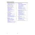
1-A. Preliminary/Final Checking and Alignment of Tape Path
Purpose: To make sure that the tape path is well stabilized. Symptom of Misalignment: If the tape path is unstable, the tape will be damaged. Note: Do not use an Alignment Tape for this procedure. If the unit is not correctly aligned, the tape may be damaged. 1. Playback a blank cassette tape and check to see that the tape runs without creasing at Guide Rollers [2] and [3], and at points A and B on the lead surface. (Refer to Fig M3 and M4.) 2. If creasing is apparent, align the height of the guide rollers by turning the top of Guide Rollers [2] and [3] with a Guide Roller Adj. Screwdriver. (Refer to Fig. M3 and M5.)
Guide Roller [2] Guide Roller [3]
3. Check to see that the tape runs without creasing at Take-up Guide Post [4] or without snaking between Guide Roller [3] and AC Head. (Fig. M3 and M5) 4. If creasing or snaking is apparent, adjust the Tilt Adj. Screw of the AC Head. (Fig. M6)
Azimuth Adj. Screw
AC Head X-Value Adj. Screwdriver
Tilt Adj. Screw
Fig. M6
1-B. X Value Alignment
Purpose: To align the Horizontal Position of the Audio/Control/ Erase Head.
AC Head
A
B Take-up Guide Post [4]
Symptom of Misalignment: If the Horizontal Position of the Audio/Control/Erase Head is not properly aligned, maximum envelope cannot be obtained at the Neutral position of the Tracking Control Circuit. 1. Connect the oscilloscope to TP004 (CPB) and TP001 (CTL) on the Main CBA. Use TP002 (RFSW) as a trigger. 2. Playback the Gray Scale of the Alignment Tape (FL6NS8) and confirm that the PB FM signal is present. 3. Set the Tracking Control Circuit to the center position by pressing CH UP button then � PLAY � button on the unit. (Refer to note on bottom of page 2-3-4.)
Fig. M3
Lead Surface of Cylinder
Tape
Fig. M4
4. Use the X-Value Adj. Screwdriver so that the PB FM signal at TP004 (CPB) is maximum. (Fig. M6) 5. Press CH UP button on the unit until the CTL waveform has shifted by approx. +2msec. Make sure that the envelope is simply attenuated (shrinks in height) during this process so that you will know the envelope has been at its peak.
Correct
Guide Roller Tape
Incorrect
Take-up Guide Post Tape
Fig. M5
2-3-3
T6300MA
|
|
|
> |
|