|
|
|
Who's Online
There currently are 6043 guests online. |
|
Categories
|
|
Information
|
|
Featured Product
|
|
|
 |
|
|
There are currently no product reviews.
 ;
First of all I must say that I received the manual in just a few minutes after placing the order. The copy is well done and very readable. I will buy others soon... Thanks, Meyer
 ;
Good service manual. I gat all I want. Copy is good, but could be better. All clear and useful. I sincerely recommend.
;
The schematic is very helpful and the images are very good.The schematic is very helpful and the images are very good.The schematic is very helpful and the images are very good.The schematic is very helpful and the images are very good.The schematic is very helpful and the images are very good.The schematic is very helpful and the images are very good.
;
Welcome. The scheme is clearly helped me to repair. Worth to download it.
;
Excellent manual, very clear, technical specification provided, useful information regarding adjustment and set up.
1-2
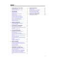
TABLE OF CONTENTS
Page Front page .............................................................................. 1-1 Table of contents ................................................................... 1-2 Survey of sets and features ................................................... 1-3 Survey of sets and boards ..................................................... 1-4
V. EXPLODED VIEWS AND PARTS LISTS
Mechanical parts list .............................................................. 5-1 Electrical parts list .................................................................. 5-4
III. SCHEMATICS
Interconnection wiring diagram .............................................. 3-1 Block diagram - Tuner1, TV ................................................... 3-2 Block diagram - Power Supply, Large Signal,TXT ................ 3-3 Block diagram - In/Out, Audio ................................................ 3-4 Block diagram - Tuner2, Video .............................................. 3-5 Block diagram - Central Control, Deck Electronics ............... 3-6 TV Board (TVB) Power Supply (PS) - Schematic diagram .............................. 3-7 Deflection (LS) - Schematic diagram ..................................... 3-8 Tuner 1 (TU1) - Schematic diagram ...................................... 3-9 TV Processing (TV) - Schematic diagram ........................... 3-10 Input/Output (IO_1) - Schematic diagram ........................... 3-11 View Selector Audio (SF) - Schematic diagram .................. 3-12 Amplifier (AMP) - Schematic diagram ................................. 3-13 Teletext Controller (COTV) - Schematic diagram ................ 3-14 Recorder Unit Board (RUB) Power Supply (PS) - Schematic diagram ............................ 3-15 Central Control 1 (AIO1) - Schematic diagram .................... 3-16 Central Control 2 (AIO2) - Schematic diagram .................... 3-17 Deck Electronics (DE) - Schematic diagram ....................... 3-18 Clock, VPS, Buzzer (CVB) - Schematic diagram ................ 3-19 Tuner 2 (TU2) - Schematic diagram .................................... 3-20 Sound Processing (AP) - Schematic diagram ..................... 3-21 FM-Audio Processing (AF) - Schematic diagram ................ 3-22 Linear Audio Processing (AL) - Schematic diagram ............ 3-23 Video Signal Processing (VS) - Schematic diagram ........... 3-24 SECAM Processing (VSEC) - Schematic diagram ............. 3-25 Head Amplifier (HA) - Schematic diagram .......................... 3-26 Headphone, Front-AV Board (HPAV) Schematic diagram .............................................................. 3-27 CRT-Board (PT) Schematic diagram .............................................................. 3-28 Audio Board (APDOD) Pre Amplifier (ACO) - Schematic diagram ........................... 3-29 Audio Processing (AF2) - Schematic diagram .................... 3-30 Sound Feature Board (SFD) Schematic diagram .............................................................. 3-31 Cinch Out, Scart 2 Board (DOSCD) Schematic diagram .............................................................. 3-32 Keys & Display Board (KB1D) Schematic diagram .............................................................. 3-33 Key Board (KB2D) Schematic diagram .............................................................. 3-34 Mainsfilter Board (MFSWD) Schematic diagram .............................................................. 3-34 Variant list Tuner 1 - TV Board (TVBAD) .............................................. 3-35 Tuner 2- Recorder Unit Board (RUBAD) ............................. 3-36
IV. CIRCUIT BOARD DIAGRAMS
Sound Feature Board (SFD) .................................................. 4-1 Mainsfilter Board (MFSWD) ................................................... 4-1 Audio Board (APDOD) ............................................................ 4-1 TV Board (TVBCD), CRT Board, HPAV Board, Switch Board .. Components side .................................................................... 4-2 Copper side ............................................................................ 4-5 TV Board (TVBDD), CRT Board, HPAV Board, Switch Board .. Components side .................................................................... 4-6 Copper side ............................................................................ 4-9 Recorder Unit Board (RUB2D) Components side ................................................................. 4-10 Copper side .......................................................................... 4-11 Cinch Out, Scart 2 Board (DOSCD) .................................... 4-12 Keys & Display Board (KB1D, KB2D) ................................ 4-12
|
|
|
> |
|