|
|
|
Who's Online
There currently are 6043 guests online. |
|
Categories
|
|
Information
|
|
Featured Product
|
|
|
 |
|
|
There are currently no product reviews.
 ;
At $5,00 certainly good bang for your buck. Includes electric schematics as well as exploded parts view + parts list for reordering. Unfortunately no details on the PCB contents or working, but then again, this is not overly complex. Best bonus: this manual does contain the heavily searched for LED error codes as well as descriptions for test operation. Haven't gotten around to fixing the machine yet, one thing the manual won't do for you is getting it out of the kitchen assembly :-(
;
It`s not your fault tear down is rather incomplete. It doesn`t have complete instructions as to deconstruction for repair.
 ;
THANK YOU FOR A GOOD TRANSACTION, NICE COPY, CLEAR
;
Very Good! All the diagram are easy to read, and its complete.
;
This was an excellent source of detailed assembly information on a device which is at least 12 years old. A very lucky find, coupled with great service.
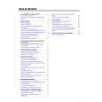
1-2
TABLE OF CONTENTS
Page Front page .............................................................................. 1-1 Table of contents ................................................................... 1-2 Survey of sets and features ................................................... 1-3 Survey of sets and boards ..................................................... 1-4
V. EXPLODED VIEWS AND PARTS LISTS
Mechanical parts list .............................................................. 5-1 Electrical parts list .................................................................. 5-4
III. SCHEMATICS
Interconnection wiring diagram .............................................. 3-1 Block diagram - Tuner1, TV ................................................... 3-2 Block diagram - Power Supply, Large Signal,TXT ................ 3-3 Block diagram - In/Out, Audio ................................................ 3-4 Block diagram - Tuner2, Video .............................................. 3-5 Block diagram - Central Control, Deck Electronics ............... 3-6 TV Board (TVB) Power Supply (PS) - Schematic diagram .............................. 3-7 Deflection (LS) - Schematic diagram ..................................... 3-8 Tuner 1 (TU1) - Schematic diagram ...................................... 3-9 TV Processing (TV) - Schematic diagram ........................... 3-10 Input/Output (IO_1) - Schematic diagram ........................... 3-11 View Selector Audio (SF) - Schematic diagram .................. 3-12 Amplifier (AMP) - Schematic diagram ................................. 3-13 Teletext Controller (COTV) - Schematic diagram ................ 3-14 Recorder Unit Board (RUB) Power Supply (PS) - Schematic diagram ............................ 3-15 Central Control 1 (AIO1) - Schematic diagram .................... 3-16 Central Control 2 (AIO2) - Schematic diagram .................... 3-17 Deck Electronics (DE) - Schematic diagram ....................... 3-18 Clock, VPS, Buzzer (CVB) - Schematic diagram ................ 3-19 Tuner 2 (TU2) - Schematic diagram .................................... 3-20 Sound Processing (AP) - Schematic diagram ..................... 3-21 FM-Audio Processing (AF) - Schematic diagram ................ 3-22 Linear Audio Processing (AL) - Schematic diagram ............ 3-23 Video Signal Processing (VS) - Schematic diagram ........... 3-24 SECAM Processing (VSEC) - Schematic diagram ............. 3-25 Head Amplifier (HA) - Schematic diagram .......................... 3-26 Headphone, Front-AV Board (HPAV) Schematic diagram .............................................................. 3-27 CRT-Board (PT) Schematic diagram .............................................................. 3-28 Audio Board (APDOD) Pre Amplifier (ACO) - Schematic diagram ........................... 3-29 Audio Processing (AF2) - Schematic diagram .................... 3-30 Sound Feature Board (SFD) Schematic diagram .............................................................. 3-31 Cinch Out, Scart 2 Board (DOSCD) Schematic diagram .............................................................. 3-32 Keys & Display Board (KB1D) Schematic diagram .............................................................. 3-33 Key Board (KB2D) Schematic diagram .............................................................. 3-34 Mainsfilter Board (MFSWD) Schematic diagram .............................................................. 3-34 Variant list Tuner 1 - TV Board (TVBAD) .............................................. 3-35 Tuner 2- Recorder Unit Board (RUBAD) ............................. 3-36
IV. CIRCUIT BOARD DIAGRAMS
Sound Feature Board (SFD) .................................................. 4-1 Mainsfilter Board (MFSWD) ................................................... 4-1 Audio Board (APDOD) ............................................................ 4-1 TV Board (TVBCD), CRT Board, HPAV Board, Switch Board .. Components side .................................................................... 4-2 Copper side ............................................................................ 4-5 TV Board (TVBDD), CRT Board, HPAV Board, Switch Board .. Components side .................................................................... 4-6 Copper side ............................................................................ 4-9 Recorder Unit Board (RUB2D) Components side ................................................................. 4-10 Copper side .......................................................................... 4-11 Cinch Out, Scart 2 Board (DOSCD) .................................... 4-12 Keys & Display Board (KB1D, KB2D) ................................ 4-12
|
|
|
> |
|