|
|
|
Who's Online
There currently are 5557 guests online. |
|
Categories
|
|
Information
|
|
Featured Product
|
|
|
 |
|
|
There are currently no product reviews.
 ;
Great product. Recieved it fast...exactly as advertised.
;
Manuals were delivered promptly and were correct as advertised. No issues with the download link which was provided promptly after everything was processed. Very pleasant experience
;
Paid for service manual & got the download fast - worth a visit if you need a service manual
;
It's the manual, I am searching for. Now I am able to repair my Braun A501.
 ;
Great service manual. Unfortunately on page no. 41 there are some details which i can't read.
ALIGNMENT PROCEDURES OF MECHANISM
[ 14PV120/07, 14PV125/ ( 01, 07, 39, 58 ), 14PV225/ ( 01, 07, 39, 58 ), 14PV422/ ( 01, 07, 39, 58 ), 14PV425/07 ]
The following procedures describe how to align the individual gears and levers that make up the tape loading/unloading mechanism. Since information about the state of the mechanism is provided to the System Control Circuit only through the Mode Switch, it is essential that the correct relationship between individual gears and levers be maintained. All alignments are to be performed with the mechanism in Eject mode, in the sequence given. Each procedure assumes that all previous procedures have been completed. IMPORTANT: If any one of these alignments is not performed properly, even if off by only one tooth, the unit will unload or stop and it may result in damage to the mechanical or electrical parts.
Alignment 1 Loading Arm (SP) and (TU) Assembly
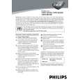
Install Loading Arm (SP) and (TU) Assembly so that their triangle marks point to each other as shown in Fig. AL2.
Alignment 2 Mode Gear
Keeping the two triangles pointing at each other, install the Loading Arm (TU) Assembly so that the last tooth of the gear meets the most inside teeth of the Mode Gear. See Fig. AL2.
Triangle Marks Alignment 1 Loading Arm (SP) Assembly Last Tooth Alignment 2
Alignment points in Eject Position
Loading Arm (TU) Assembly
Top View
Most inside teeth of Mode Gear Mode Gear Alignment 3
Fig. AL2
Alignment 3 Cam Gear (A), Rack Assembly
Install the Rack Assembly so that the first tooth on the gear of the Rack Assembly meets the first groove on the Cam Gear (A) as shown in Fig. AL3.
Top View Cam Gear (A)(HI) Alignment 3
Bottom View
Alignment 1 First tooth
Alignment 2
Fig. AL1
First groove Gear on Rack Assembly on the Cam Gear (A)(HI)
Fig. AL3 2-4-17 T6410APM
|
|
|
> |
|